
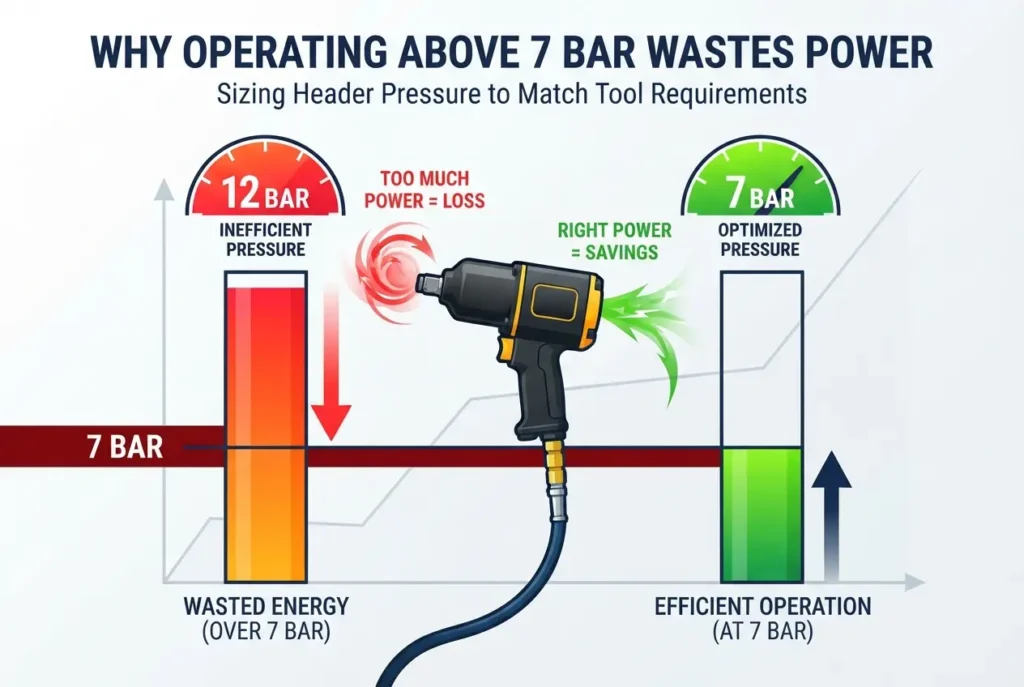
Walk across the factory floor of almost any manufacturing plant, and you will likely find the compressor discharge gauge set anywhere between 8 and 10 bar. When asked why the pressure is cranked so high, the response from maintenance teams is nearly universal: “The machines run sluggishly if we lower it,” or “We need a buffer to prevent low-pressure trips.” It feels like a safe, proactive strategy. After all, nobody gets faulted when downstream pneumatic tools have plenty of pressure to cycle reliably.
However, running an entire distribution network well above 7 bar simply to satisfy a handful of demanding points is one of the most expensive operational habits in industrial manufacturing. Compressed air is already one of the costliest utilities in modern industry, requiring immense electrical energy to produce usable mechanical work. Forcing a compressor to generate artificial overpressure creates an ongoing financial drain on your utility bill, accelerates wear on air-end components, and magnifies parasitic waste across your entire distribution header.
To curb unnecessary energy expenses, facilities must shift from an “over-pressurize and forget” mindset to engineered header pressure sizing. By understanding your real point-of-use requirements and eliminating downstream flow restrictions, you can align supply pressure directly with tool demand, unlocking substantial energy savings without compromising production speed.
The Physics of Overpressure: Why Higher Bar Drives Power Consumption
Every compressor works against the atmospheric baseline to squeeze air molecules into a confined receiver. As the discharge setpoint climbs higher, the internal compression ratio increases. The compressor motor must overcome heavier resistance on every revolution, which draws significantly more electrical current from the plant grid. Operating a standard screw compressor at 8.5 or 9 bar instead of 6.5 to 7 bar forces the motor to run continuously near its peak thermal and electrical limits.
This excess energy does not vanish harmlessly. The surplus work demanded by overpressure translates largely into heat. The motor runs hotter, the lubricant degrades faster, and the oil cooler works overtime to reject thermal load. Over time, elevated discharge pressures reduce the operational life of valves, mechanical seals, and bearings, necessitating more frequent servicing and shortening the mean time between overhauls.
Furthermore, compressor output capacity drops at higher pressures. Because the air inside the compression chamber must be compressed to a denser state before discharge, the actual volume of free air delivered per motor revolution decreases. You end up paying more in electricity for every unit of delivered flow, simultaneously eroding both machine efficiency and volumetric output.
Artificial Demand: The Compounding Cost of Higher Distribution Pressure
Higher header pressure does not merely strain the compressor motor; it radically escalates downstream consumption through a phenomenon known as artificial demand. Pneumatic components operating without point-of-use pressure regulation consume more mass flow of air than their design requires when supplied at elevated pressures. An unregulated blow-off nozzle or air cylinder running at 8.5 bar consumes far more cubic feet of air per stroke than the exact same device operating smoothly at 6 bar.
Artificial demand also magnifies system leaks. In any industrial piping network, tiny orifices exist at push-in fittings, threaded joints, quick-disconnect couplers, and valve seals. Because mass flow through an orifice increases alongside pressure, raising the main header pressure forces significantly more air through every open fissure across your plant. Running an elevated pressure profile turns minor leaks into major energy drains, masking system inefficiencies and driving unnecessary cycle times.
Before jumping to the conclusion that higher header pressure is your only safeguard against machine stall-outs, smart facilities look deeper into distribution integrity. Plant engineers often combine systematic leak control with regular audits—such as learning how to conduct an ultrasonic compressed air leak audit in manufacturing plants—to cut artificial demand at the root rather than trying to overpower leaks with higher discharge settings.
Pressure Drop vs. Supply Shortage: Identifying the Real Bottlenecks
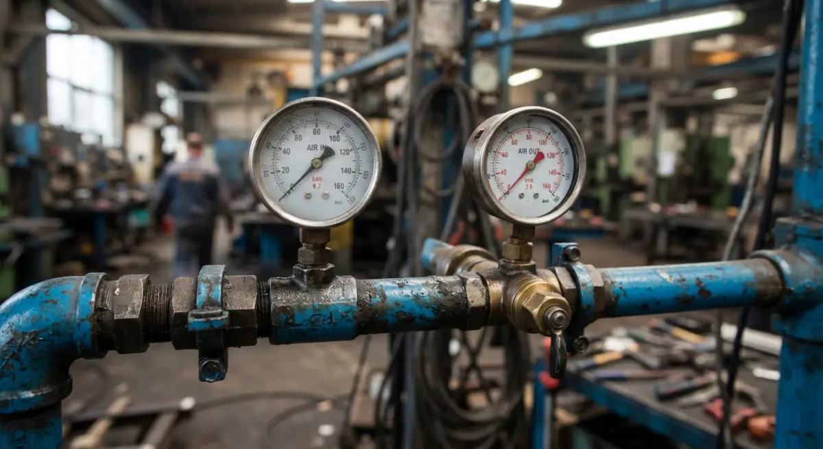
When an operator reports that an actuator, pneumatic drill, or packaging arm lacks punching power, the immediate reaction is often to walk into the compressor room and turn up the master controller. But in the vast majority of industrial facilities, the compressor is not the problem. The true culprit is excessive dynamic pressure drop between the compressor room and the tool.
Dynamic pressure drop occurs when compressed air travels through undersized pipe runs, rough internal wall surfaces, congested filtration units, undersized flex hoses, or restrictive quick-connect fittings. While the gauge on the compressor tank might read 8.5 bar during static conditions, the pressure at the tool can easily plummet down to 5 bar during active duty cycles. Raising the central compressor pressure to 9.5 bar simply attempts to blast through downstream piping friction, spending expensive kilowatt-hours to compensate for inadequate plumbing.
Solving this dynamic drop requires addressing distribution layout and materials. Replacing restrictive, corroding black-iron pipe with high-efficiency distribution lines is a proven remedy; comparing aluminum vs gi piping for industrial compressed air pressure drop and lifetime cost comparison demonstrates how smooth inner walls drastically cut transport losses. Similarly, adopting modern header layouts—like evaluating loop ring main vs deadend air header piping which layout reduces pressure drop better—creates balanced multi-directional flow that eliminates localized pressure starve without requiring higher compressor settings.
How to Size and Match Header Pressure to Tool Requirements
Most standard pneumatic tools—such as cylinders, directional solenoid valves, diaphragm pumps, and air wrenches—are engineered to deliver their full rated force and speed at 6 to 6.3 bar. Any pressure supplied beyond this baseline provides negligible torque or speed improvements while drastically shortening seal life. To dial in the ideal header pressure, plant managers should implement an engineered sizing strategy:
- Audit Critical Machine Demands: List every pneumatic asset on your shop floor and note its minimum required operating pressure. Identify if 90% of your machinery needs only 6 bar, while a single legacy machine claims it requires 8 bar.
- Isolate High-Pressure Outliers: Never force an entire facility header to run at 8.5 bar for the sake of one or two specialized operations. Instead, drop the main header to match the majority requirement, and install a dedicated local pressure booster or an isolated small-footprint compressor for high-pressure consumers.
- Enlarge Interconnects and Drop Lines: Upgrade undersized 1/4-inch supply hoses and quick-disconnect fittings to high-flow safety couplers and 3/8-inch or 1/2-inch whip hoses at high-demand machinery to eliminate dynamic restriction.
- Install Dedicated Point-of-Use Storage: Heavy, intermittent demands—such as pulse-jet dust collectors or rapid-stroke clamping stations—frequently cause momentary localized pressure drops. Positioning a small auxiliary receiver tank right next to the demand point buffers the surge without pulling down the central header.
Practical Steps: Incrementally Lowering Your Header Pressure
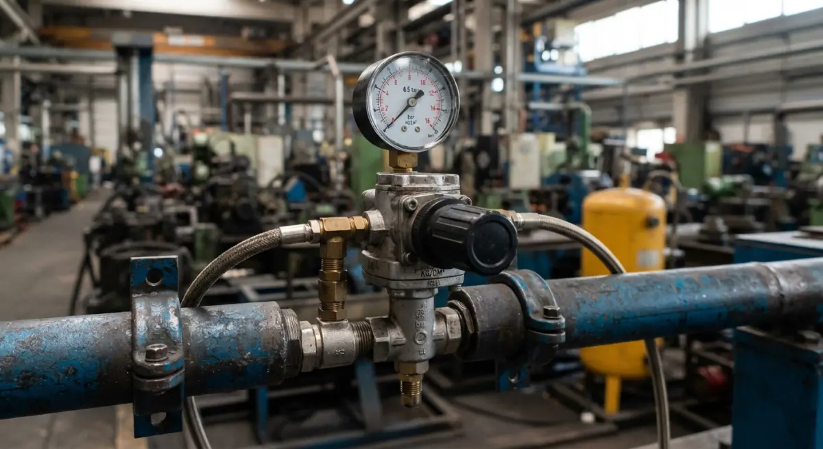
Lowering your facility’s header pressure should not be done abruptly in a single afternoon. Instead, adopt a measured, step-down approach to find your system’s true operational sweet spot while observing performance:
First, inspect downstream point-of-use Filter-Regulator-Lubricator (FRL) assemblies. Ensure that individual machine regulators are set precisely to the manufacturer’s recommended operating specification. If a machine regulator is wide open, adjust it down to its rated operating boundary.
Next, lower your compressor’s discharge pressure target in small increments—approximately 0.2 bar at a time—at the start of a production week. Monitor machine cycle times, error logs, and tool responsiveness. Continue stepping the pressure down gradually across several weeks until you observe the first signs of operational resistance, then raise the setpoint by 0.2 bar. This establishes your true minimum baseline, operating your plant reliably with zero wasted energy.
For operations experiencing broad fluctuations in usage, matching pressure becomes even more manageable by pairing clean distribution with flexible drive technology. Exploring whether a fixedspeed vs vfd air compressor which is right for your factory gives you tighter pressure-band regulation, eliminating the wide pressure swings common to older load/unload machines.
Reclaim Control of Your Plant Energy Costs
Treating header pressure as a crude lever to solve downstream pneumatic issues is a costly compromise that penalizes your plant’s bottom line every minute your equipment runs. Operating above 7 bar should be a deliberate, engineered exception—not the standard default setting for industrial air systems.
By auditing tool-side demands, smoothing out piping restrictions, eliminating friction-induced pressure drop, and stepping down your central header, your plant can lower baseline energy draw, reduce component failure, and maximize compressor longevity. Take a hard look at your compressor room discharge gauges today: sizing your supply pressure to true tool requirements is the most direct, cost-free path to sustainable plant efficiency.
Frequently Asked Questions
How much energy does an air compressor waste for every 1 bar above 7 bar?
Operating an air compressor at higher pressures requires significantly more electrical power, typically increasing energy consumption by 6% to 8% for every 1 bar (14.5 psi) increase. Running above 7 bar without a process requirement also artificially increases the flow rate of unregulated end-use tools, further amplifying unnecessary power draw.
Why do most industrial pneumatic tools perform optimally at 6 to 6.3 bar instead of 7 bar or higher?
Pneumatic tools are standardized by manufacturers to reach peak torque, speed, and efficiency ratings at dynamic inlet pressures between 6.0 and 6.3 bar. Supplying higher pressures does not meaningfully increase tool productivity, but it drastically accelerates mechanical wear and increases seal failure rates.
How does elevated header pressure impact system artificial demand and compressed air leaks?
Higher header pressure directly drives up artificial demand because unregulated uses and continuous leaks consume more air volume at elevated pressures. A typical compressed air leak loses roughly 10% more mass air volume with every 1 bar increase in line pressure, turning small orifices into major energy sinks.
What steps should I take to size distribution header pressure down closer to tool requirements?
Begin by identifying the single end-use application with the highest pressure requirement and audit the delivery system to eliminate friction losses from undersized piping, clogged filters, and restrictive couplings. By reducing system-wide pressure drop to under 0.5 bar, you can safely lower the main header discharge setpoint without starving point-of-use operations.
Can point-of-use pressure boosters solve pressure drops instead of running the entire header above 7 bar?
Yes, installing dedicated local pressure boosters or small point-of-use compressors for the few tools that truly require elevated pressures allows the central system to operate below 7 bar. This targeted approach prevents the extreme energy penalties associated with pressurizing the entire facility's distribution volume to satisfy an isolated high-pressure process.