
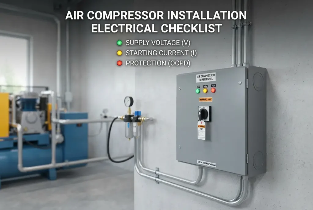
Installing an industrial air compressor is a major capital investment, yet the electrical infrastructure feeding it is frequently treated as an afterthought. Many plant managers focus heavily on the mechanical layout, selecting pipe diameters, positioning air receivers, and routing condensate drains. However, the electrical foundation dictates whether your compressor operates reliably for years or becomes plagued by nuisance tripping, premature motor burnouts, and unexplainable control panel faults.
Electric motors used in air compressors operate under demanding duty cycles. Unlike light industrial equipment that starts under minimal mechanical load, compressors must overcome immediate system backpressure, inertia, and continuous cycling. Failing to account for incoming supply voltage quality, inrush current spikes, and matched electrical protection will compromise your entire production floor. Proper planning ensures equipment longevity, lowers energy costs, and prevents sudden manufacturing halts.
Whether you are setting up a rotary screw unit in an engineering plant or expanding a manufacturing shed, following an electrical checklist is critical. Here is a comprehensive breakdown of the essential electrical factors—supply voltage stability, starting current management, and coordinated protection—you must evaluate before powering up your machine.
1. Supply Voltage Stability and Phase Balance
Industrial electric motors are designed to operate within a specific voltage tolerance, typically ±10% of their nominal rating. Operating outside this band introduces severe mechanical and thermal stresses. Low supply voltage forces the motor to draw higher current to produce the required torque to turn the compression element. This elevated current generates excessive internal heat in the motor windings, rapidly degrading insulation materials and causing insulation breakdown.
Voltage unbalance across three-phase systems is an equally dangerous, often overlooked problem. A small percentage of voltage unbalance produces a disproportionately high current unbalance in the stator windings. This imbalance generates negative-sequence magnetic fields, causing rotor heating, severe vibration, and significant efficiency losses. When evaluating fixedspeed vs vfd air compressor configurations, remember that variable frequency drives (VFDs) are also sensitive to voltage transients, sags, and phase loss, requiring clean incoming electrical power.
Before installing your compressor, log your facility’s incoming line voltage during peak operating hours. If other heavy machinery causes voltage sags when cycling on, your compressor will experience those drops. Mitigating these issues requires properly sized supply transformers, dedicated distribution sub-panels, and, in severe cases, industrial automatic voltage regulators.
2. Managing Starting Current and Inrush Loads
Starting an electric motor demands significantly more current than running it under full load. Known as locked rotor current or inrush current, this surge can draw several times the motor’s full-load amperage (FLA) for a few seconds. If your electrical infrastructure is not planned around these surges, starting the compressor will cause voltage dips across the plant, flickering lights, and false tripping of sensitive upstream electronics.
The method you select to start the compressor directly affects your electrical system design:
- Direct-On-Line (DOL) Starters: Typically limited to smaller horsepower motors. DOL starters apply full line voltage immediately, delivering maximum starting torque but producing the highest inrush current and mechanical stress on the drive belts or couplings.
- Star-Delta (Wye-Delta) Starters: A standard choice for mid-to-large fixed-speed compressors. This method starts the motor in a star configuration to reduce incoming voltage and starting current, then transitions to a delta configuration once up to speed. This approach prevents plant-wide voltage dips during startup.
- Soft Starters and Variable Frequency Drives: These solid-state systems gradually ramp up voltage and frequency, limiting the starting current to near-running levels. They eliminate electrical surges entirely and reduce mechanical shock loads.
Proper electrical design must also factor in ambient conditions. If your equipment operates in high ambient temperatures, such as why screw compressors overheat in south tamil nadu summers and how to fix it, the combined thermal stress from ambient heat and high starting currents can trip thermal overloads even when mechanical loads seem normal.
3. Sizing Conductors and Cable Runs for Voltage Drop
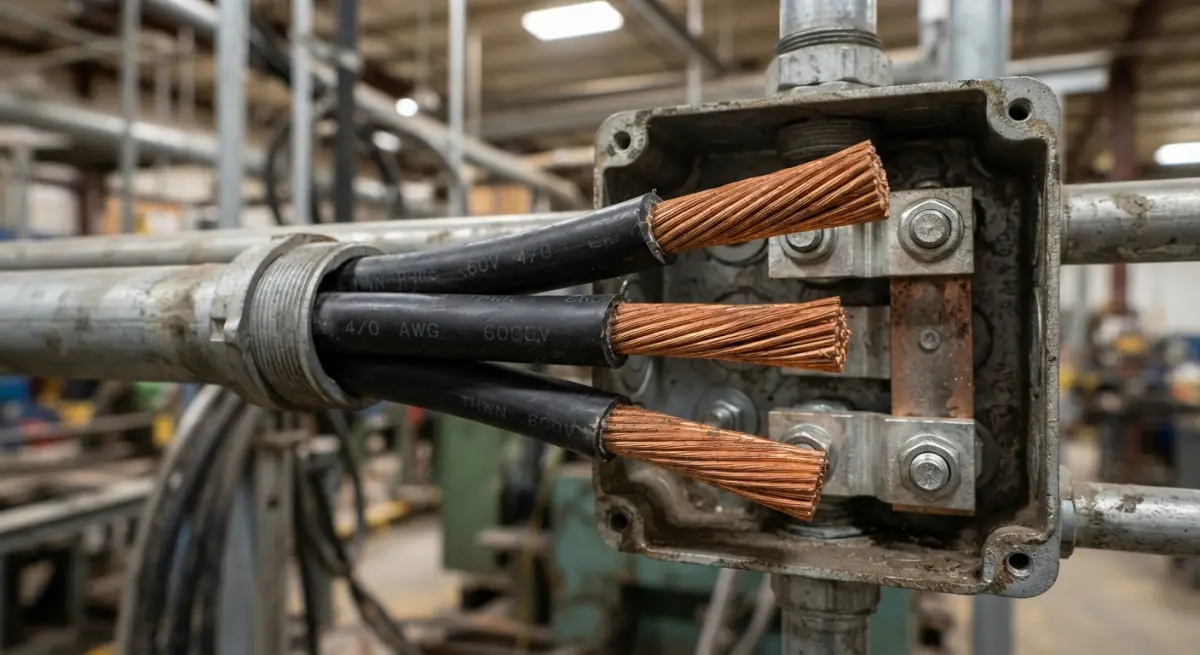
One of the most frequent mistakes during installation is sizing power cables solely based on continuous current-carrying capacity (ampacity) without calculating distance-related voltage drop. As cable run length increases, electrical resistance accumulates. If the cable is undersized over a long run, line resistance causes a significant voltage drop before the power even reaches the compressor starter terminals.
Excessive voltage drop during startup starves the motor of torque, extending the acceleration time and keeping the motor in its high-current inrush state for longer. This prolonged current draw trips breaker protection curves and risks burning contactor tips. As a best practice, total voltage drop between the main distribution board and the compressor terminals should not exceed 3% under full-load running conditions, with dedicated considerations for motor starting inrush.
4. Comprehensive Circuit Protection and Grounding
Protecting the motor and internal controls requires a multi-layered electrical protection scheme. A standard distribution breaker is insufficient to safeguard precision industrial air equipment. Your electrical installation must incorporate:
- Motor Protection Circuit Breakers (MPCBs) or MCCBs: Circuit breakers must match the motor’s starting characteristics. They must allow inrush current to pass without tripping while providing instantaneous magnetic protection against short circuits.
- Thermal and Electronic Overload Relays: These devices protect the motor against sustained operational overloads, mechanical binding inside the airend, or single-phasing events (loss of one power phase). Electronic overloads offer superior precision compared to traditional bimetallic strips.
- Phase Sequence and Phase Failure Relays: Rotary screw compressors must only rotate in one direction; reverse rotation can destroy the airend within seconds due to lack of lubrication. A reverse-phase relay prevents the motor from starting if incoming phase wiring is accidentally inverted during electrical maintenance.
- Dedicated Equipment Grounding: Proper earthing paths prevent dangerous touch voltages on the compressor frame and divert high-frequency electrical noise generated by internal microprocessors or VFD inverters, preventing control board lockups.
Practical Checklist and Inspection Tips
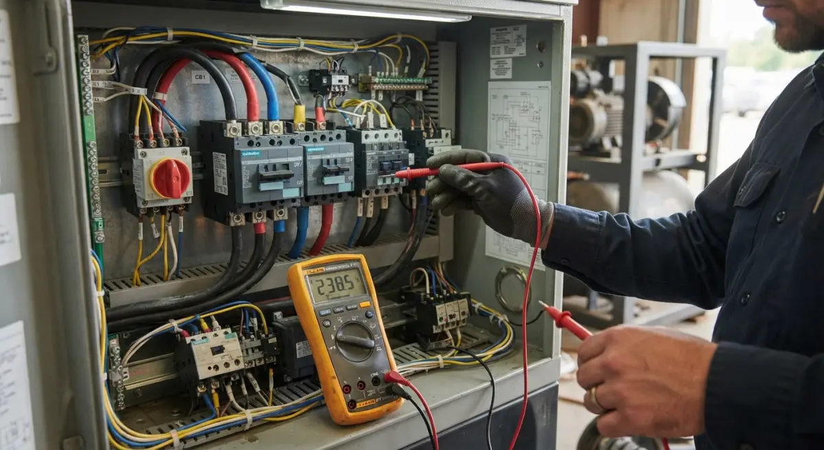
Before energizing your air compressor for the first time, have a qualified industrial electrician walk through these practical verification steps:
- Measure Static Voltage: Check phase-to-phase and phase-to-neutral voltages at the isolator switch before turning on the unit. Confirm values sit comfortably within manufacturer specifications.
- Verify Terminal Torques: Transport vibration and temperature fluctuations loosen screw lugs. Check and torque every power terminal connection inside the compressor electrical enclosure using a calibrated torque tool. Loose connections create localized heating and fire hazards.
- Check Overload Dial Settings: Ensure the overload relay dial matches the full-load current (FLA) stated on the motor nameplate, accounting for service factor and starter configuration (e.g., in a star-delta setup, the relay setting depends on whether it is placed inside or outside the delta loop).
- Test Phase Rotation: Use a phase rotation meter on the line side before energizing. “Bump” the motor momentarily while observing the directional arrow on the drive housing to ensure correct rotation.
Set Up Your Compressed Air Infrastructure for Long-Term Reliability
A mechanically robust air compressor cannot deliver reliable pneumatic power without an equally robust electrical supply. Taking the time to calculate starting currents, verify incoming line stability, size cables for distance, and configure responsive protection circuits protects your machinery and prevents costly production interruptions. If you are planning a plant installation or upgrading an existing setup, consult experienced specialists who understand the intersection of electrical design and pneumatic demands. Contact our team to request an air compressor quote and get tailored technical guidance for your facility.
Frequently Asked Questions
How do I determine if my electrical supply voltage is compatible with my air compressor?
Check the compressor's data plate for the nominal voltage and phase rating, then use a multimeter to measure the actual voltage at the disconnect switch. Ensure the measured voltage stays within the typical manufacturer tolerance of ±10% under both no-load and full-load operating conditions to prevent motor damage.
Why does my air compressor trip the circuit breaker during startup?
Air compressor electric motors draw an inrush or starting current that can be 5 to 8 times higher than their normal running current, which easily trips standard breakers. Installing a dedicated circuit with an inverse-time circuit breaker or implementing a magnetic soft-starter will accommodate this momentary current spike without nuisance tripping.
What is the difference between running current (FLA) and starting current (LRA) on a compressor?
Full Load Amps (FLA) indicates the steady-state current drawn while the motor operates at its rated horsepower, which dictates continuous wire sizing. Locked Rotor Amps (LRA) represents the extreme current drawn at the exact moment of startup to overcome mechanical inertia, which determines the required trip curve for overcurrent protection devices.
How do I choose the correct circuit breaker and wire size for an air compressor installation?
Size your branch circuit conductors to carry at least 125% of the motor's Full Load Amps (FLA) to comply with National Electrical Code (NEC) standards and prevent overheating. For circuit breaker selection, use a time-delay breaker or motor-rated dual-element fuse typically sized between 175% and 250% of the FLA to safely handle the compressor's starting surge.
Is a separate thermal overload relay required if my compressor circuit already has a breaker?
Yes, standard branch-circuit breakers only protect the system wiring from short circuits and severe ground faults, not gradual motor overheating. Dedicated thermal overload relays are necessary because they detect low-level, continuous overcurrent conditions that occur during mechanical jams or low-voltage brownouts, shutting the motor down before internal windings burn out.
Also read: How to Measure Compressor Specific Power Before Replacing an Ageing Machine