
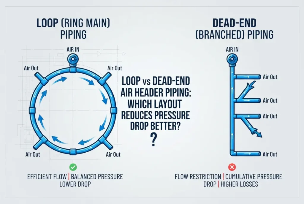
When plant managers and utility engineers notice fluctuating pneumatic pressure at their workstations, the immediate reaction is often to crank up the discharge pressure at the compressor. However, elevating generation pressure only masks the real problem while driving up energy consumption and accelerating equipment wear. In a significant number of industrial facilities, the root cause of inconsistent pressure isn’t an undersized compressor—it is a poorly designed piping distribution network that introduces excessive friction and velocity spikes.
The piping system acts as the circulatory system of your industrial facility. If it restricts airflow or creates turbulent friction, downstream tools, actuators, and packaging machines will constantly suffer from pressure drops during peak operations. When designing or retrofitting an air network, engineers typically choose between two fundamental configurations: a dead-end (linear or branch) header and a loop (ring main) header system. Understanding how these two layouts perform under dynamic factory demands is crucial for maintaining steady air pressure and minimizing operational costs.
Before committing capital to distribution hardware, you must understand how layout geometry interacts with fluid dynamics. Deciding between a ring main and a dead-end layout determines how efficiently air moves across your shop floor, impacts system redundancy, and governs your total cost of ownership over decades of operation.
Understanding Dead-End Air Header Systems
A dead-end air header, often called a linear, straight-run, or branched system, is the traditional layout found in many older or smaller workshops. In this configuration, a central main line extends from the compressor room down the length of the production floor, terminating abruptly at the furthest point. Individual drop lines branch off along the way to supply specific machines, tools, and processes.
The primary attraction of a dead-end header is its initial simplicity and lower upfront installation cost. It uses fewer linear meters of pipe, requires fewer fittings, and takes less time to install during facility setup. In small facilities where air demand is strictly concentrated near the utility room, or for businesses selecting the right screw compressor setup for cnc machining and metal fabrication workshops with isolated pneumatic stations, a dead-end line can serve simple operational requirements.
However, the fluid mechanics of a dead-end system carry severe performance limitations. Because air travels in a single direction along a single path, every drop line takes a bite out of the total available volume and pressure. Friction accumulates continuously along the pipe wall over distance. As a result, workstations located at the terminal end of the line consistently experience lower baseline pressure and severe starvation whenever heavy-demand equipment upstream kicks in simultaneously.
How a Loop (Ring Main) Distribution Network Works
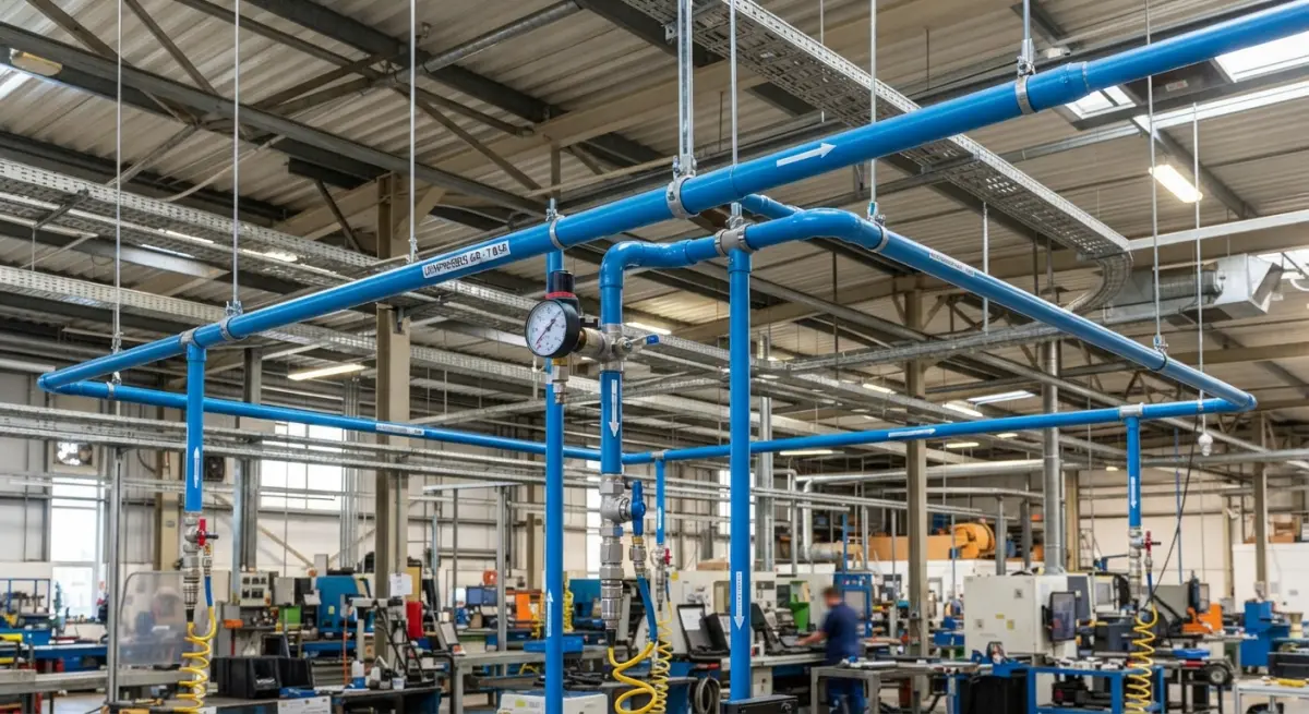
A loop or ring main system interconnects the entire header into a continuous, closed circuit that encircles the production perimeter or production zones. The discharge from the compressor and receiver tank feeds into this continuous ring, allowing compressed air to flow in two opposite directions at the same time.
Because the air has dual pathways to travel, the effective cross-sectional capacity of the distribution header is virtually doubled. When a high-volume consumer at the far end of the plant opens its valve, air rushes to meet that demand from both the clockwise and counter-clockwise legs of the loop. This dual-feed mechanism prevents localized pressure drops by balancing flow distribution across the entire facility.
Beyond fluid balance, a properly designed ring main incorporates sectioning isolation valves throughout the perimeter. If maintenance, line expansion, or leak repairs are needed in one manufacturing bay, that specific segment can be isolated without shutting down the entire plant. Combining this layout with efficient materials—as detailed in our guide on aluminum vs gi piping for industrial compressed air pressure drop and lifetime cost comparison—results in an exceptionally smooth, low-turbulence air conveyance network.
Which Layout Reduces Pressure Drop Better?
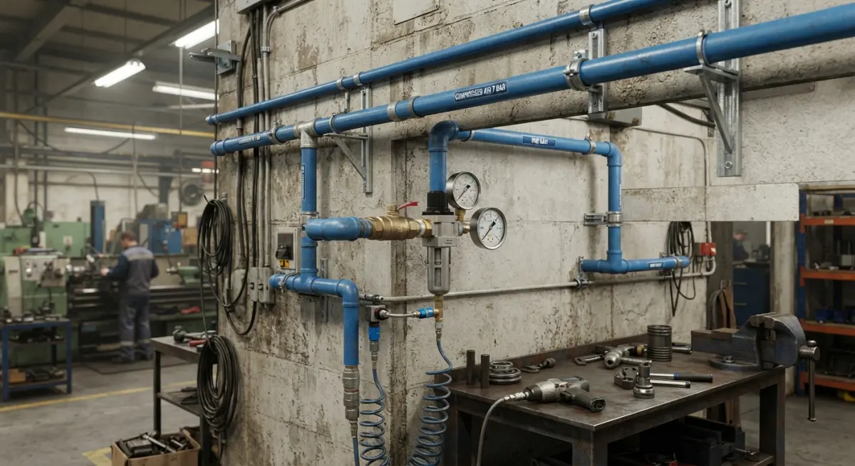
From an engineering perspective, the loop (ring main) header is definitively superior at reducing pressure drop. Pressure drop in any compressed air system is governed by air velocity, pipe diameter, pipe wall smoothness, and the distance air must travel. In fluid dynamics, friction losses increase dramatically as air velocity climbs.
In a dead-end line, all the volumetric flow required by downstream machines must push through a single pipe cross-section, which forces air velocity higher and generates heavy friction against the pipe walls. If an intermittent high-demand machine activates halfway down the line, downstream tools immediately face an acute transient pressure drop.
In a loop system, dividing the volumetric flow into two parallel paths immediately cuts air velocity within the header pipes. Lower velocity yields significantly lower friction loss per meter of pipe. Furthermore, the effective distance compressed air must travel from the supply point to the furthest workstation is cut roughly in half compared to a dead-end run spanning the same shop floor footprint. By lowering velocity and shortening the travel path, the ring main ensures point-of-use pressure remains stable, predictable, and remarkably consistent across all shifts.
Comparing Operational and Maintenance Factors
While pressure stability is the primary performance metric, long-term operational factors also tilt heavily in favor of ring main architectures:
- Condensate and Moisture Management: In dead-end systems, moisture carried through the air tends to pool at low points or collect violently at the blind termination flange, leading to accelerated internal corrosion and line contamination. A properly pitched loop system directs condensate predictably toward targeted drain legs and automated traps, preventing water carryover into sensitive tools.
- System Expansion: Expanding a dead-end line requires extending pipe further away from the supply room, compounding downstream starvation. Adding new workstations to a loop requires simply tapping into the nearest overhead header segment, maintaining system balance without choking the existing drops.
- Air Quality and Filtration: Ring layouts minimize sudden velocity surges that can sweep accumulated scale or oil aerosols downstream into high-precision machinery, preserving point-of-use filter life.
- Leak Management: In dead-end setups, repairing a pipe leak or replacing a drop valve often requires depressurizing the entire header, bringing all production to a halt. In contrast, facilities running routine maintenance—such as knowing how to conduct an ultrasonic compressed air leak audit in manufacturing plants—can isolate specific segments in a looped layout and perform fixes while remaining production bays keep running.
Practical Design Tips for Industrial Air Headers
Implementing a loop system correctly requires more than just connecting pipes into an arbitrary circle. Keep these engineering principles in mind during installation:
Use Overhead Loops with Swan-Neck Drops: Run the main loop elevated above the production bays. Always take take-off drop lines from the top of the header pipe using a 180-degree bend (swan neck or gooseneck) before routing down to workstation level. This simple design prevents any moisture running along the bottom of the main header from draining into your pneumatic machinery.
Size the Header Generously: Sizing pipe based strictly on connection port sizes at the compressor is a frequent mistake. Always size the main loop diameter for your planned future capacity, not just current consumption. The cost difference between pipe sizes during initial installation is minor compared to the cost of retrofitting an undersized line later.
Incorporate Sub-Loops for Heavy Consumers: If a specific area of your facility operates heavy air consumers—such as high-speed blast cabinets, packaging lines, or pneumatic presses—isolate that zone with its own dedicated secondary sub-loop connected back to the primary main loop. Placing a dedicated secondary receiver tank in that zone will buffer peak transient draws and shield the rest of the factory from localized pressure dips.
Conclusion
When comparing dead-end air headers with ring main layouts, the loop piping architecture is undeniably the better choice for reducing system pressure drop, maintaining steady operating pressures, and curbing compressor energy waste. While a dead-end pipe might save initial material costs on small, single-tool runs, its severe fluid resistance, vulnerability to pressure dips, and lack of operational redundancy make it an expensive handicap for active manufacturing operations.
Investing in a well-engineered, looped compressed air header ensures your downstream machines operate at peak performance without forcing you to overcompensate by driving up compressor discharge pressures. If you are planning a plant expansion, redesigning your utility headers, or seeking to eliminate chronic pressure drops across your facility, contact the technical specialists at request an air compressor quote to design an optimized, energy-efficient compressed air piping layout tailored to your workflow.
Frequently Asked Questions
How does a loop air header piping layout reduce pressure drop compared to a dead-end system?
A loop (ring main) layout reduces pressure drop by providing two parallel paths for compressed air to reach any point of demand, which effectively cuts the air velocity in half. Because frictional pressure drop is proportional to the square of velocity, halving the flow speed through the network dramatically decreases overall friction losses across the system.
Why does a dead-end air header cause intermittent pressure drops at end-of-line drop points?
Dead-end systems force the entire volume of compressed air through a single directional path, causing cumulative friction losses that increase the farther a machine is from the compressor. When high-demand equipment downstream activates, it quickly starves nearby tools of pressure because the supply cannot be dynamically routed from an alternate direction.
Can switching from a dead-end header to a ring main layout lower air compressor energy costs?
Yes, switching to a ring main design can significantly lower operating costs because minimizing distribution pressure drop allows you to lower the compressor's discharge setpoint. Reducing generation pressure by just 2 psi yields approximately a 1% reduction in compressor energy consumption while still maintaining required tool pressure.
When is a dead-end compressed air piping layout preferred over a closed-loop system?
A dead-end layout is typically preferred for small workshops, single straight-line facilities, or applications with limited, steady air demands where the cost of returning pipework is unjustifiable. It is also selected for modular, temporary expansions where piping installation simplicity and low upfront material costs outweigh long-term pressure efficiency gains.
How should isolation valves be configured in a loop air header to maintain pressure during maintenance?
Isolation valves should be strategically installed at sectional intervals around the perimeter loop, typically between major work zones or departments. This sectional placement allows technicians to shut down and service one specific branch while air continues to flow through the opposite side of the ring, ensuring uninterrupted pressure to the rest of the plant.
Also read: Compressed Air Dew Point: Why Atmospheric Dew Point and Pressure Dew Point Are Not the Same